



What Is a Lithium Battery Pack and How Does It Work?
A lithium battery pack is more than a group of cells wrapped in a case. It is an engineered energy system that stores electricity chemically and releases it when equipment needs power. Inside, individual cells connect in series, parallel, or both, depending on the required voltage and capacity. A compact pack may power a laptop, while a larger design can support an electric vehicle or stationary storage system. Labels can mislead. Its real performance depends on cell quality, temperature, wiring, software, and daily use.
During discharge, chemical reactions push electrons through an external circuit, producing usable current. The battery management system monitors voltage, temperature, and current across the pack. It can balance cells and reduce charging or discharging when conditions become unsafe. A charger then reverses the electrochemical process, moving energy back into the cells. This process is not perfectly efficient. Some energy becomes heat, especially under high loads or cold conditions. Understanding these limits helps users choose suitable chargers, storage conditions, and replacement schedules. It also prevents a common mistake: judging a pack only by its advertised capacity. Capacity matters, but so do lifespan, safety controls, thermal design, and maintenance. No pack is perfect. Even well-designed systems age, lose capacity, and respond differently to real-world conditions. This guide explains how the main parts work together, what specifications mean, and where practical risks deserve careful attention.
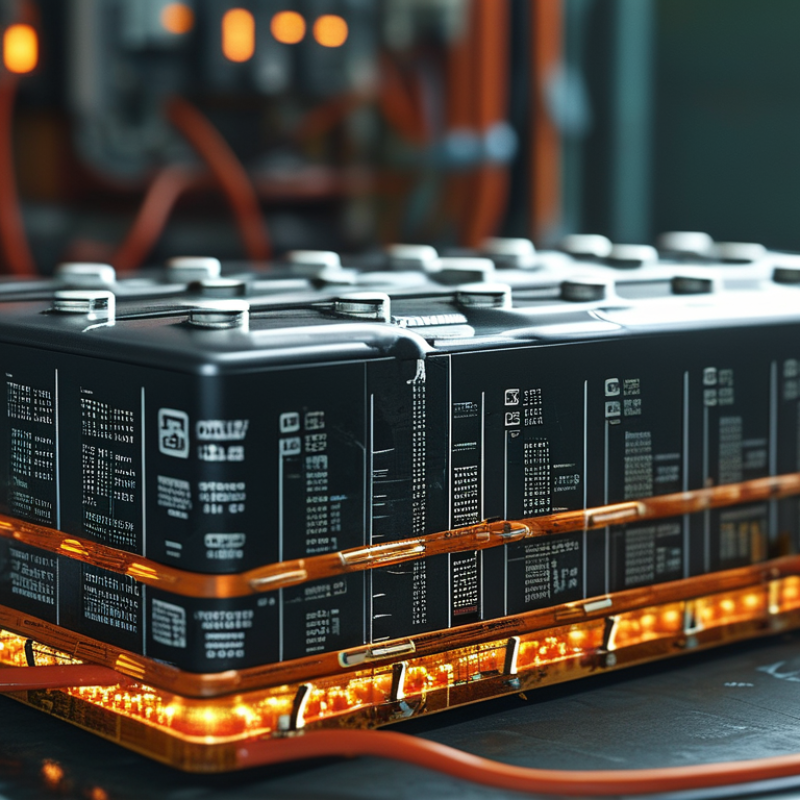
Lithium Battery Packs Defined: Cells, Modules, BMS, and Enclosures
What Is a lithium battery pack and How Does It Work?
Lithium Battery Packs Defined: Cells, Modules, BMS, and Enclosures
A lithium battery pack is an engineered system, not merely a group of loose cells. Individual cells store energy through controlled chemical reactions. They connect in series to raise voltage or in parallel to increase capacity. Cell chemistry, temperature, age, and internal resistance affect real-world performance.
Several cells may form a module, making assembly and service more manageable. Modules then connect with busbars, sensors, and insulated wiring. A battery management system, or BMS, monitors voltage, current, and temperature. It can balance cells, limit charging, and disconnect the pack during dangerous conditions. The BMS is essential, but it is not a repair mechanism.
The enclosure protects the internal parts from impact, moisture, dust, and accidental contact. It also supports cooling and prevents movement that could damage connections. In practical inspections, weak seals or poor thermal paths often matter as much as cell quality. A simple cell count is not enough. The pack’s design must match its load, charger, operating environment, and maintenance needs. Even a sophisticated BMS cannot correct a crushed cell or a badly designed enclosure. That limitation deserves more attention.
What Is a Lithium Battery Pack and How Does It Work? — Lithium Battery Packs Defined: Cells, Modules, BMS, and Enclosures
| Pack Element | What It Is | Primary Function | Typical Data or Range | How It Works in the Pack | Safety and Design Considerations |
|---|---|---|---|---|---|
| Lithium-Ion Cell | A single electrochemical unit containing a positive electrode, negative electrode, separator, electrolyte, and current collectors. | Stores and releases electrical energy through reversible movement of lithium ions between the electrodes. | Nominal voltage: approximately 3.2–3.7 V, depending on chemistry. Common formats: cylindrical, prismatic, and pouch. | Cells are connected in series to increase voltage and in parallel to increase capacity and current capability. | Cell chemistry, temperature, state of charge, age, and manufacturing consistency affect performance and safety. |
| Cell Chemistry | The specific cathode and anode materials used inside a lithium-ion cell. | Determines energy density, power capability, operating life, voltage characteristics, and thermal behavior. | Common examples include lithium iron phosphate and nickel-based lithium-ion chemistries. Typical full-charge voltage may range from approximately 3.6 V to 4.2 V per cell, depending on chemistry. | The selected chemistry establishes the electrical limits that the charger, BMS, and load must follow. | Charging limits must match the chemistry. Different chemistries should not be mixed within the same battery pack. |
| Series Connection | An electrical arrangement in which the positive terminal of one cell or module connects to the negative terminal of the next. | Raises the total voltage of the battery pack. | Example: a 10-series configuration using cells with a 3.6 V nominal voltage provides approximately 36 V nominal. | The pack voltage is approximately the cell voltage multiplied by the number of series groups. | Voltage differences between series groups must be monitored to prevent overcharge or over-discharge of individual groups. |
| Parallel Connection | An electrical arrangement in which cells or series strings share common positive and negative connections. | Increases ampere-hour capacity and can increase the available current. | Example: two identical 10 Ah cells connected in parallel provide approximately 20 Ah at the same nominal voltage. | Parallel cells or strings operate at nearly the same voltage while sharing charge and discharge current. | Cells should be matched for chemistry, capacity, age, internal resistance, and state of charge before parallel connection. |
| Battery Module | A mechanically organized group of interconnected cells, often with electrical sensing and structural supports. | Simplifies assembly, service, thermal management, and integration into a larger pack. | A module may contain a single series group or multiple series-parallel cell arrangements. Its voltage and capacity depend on the cell configuration. | Several modules can be connected in series, parallel, or a combination to achieve the required pack specifications. | Module interconnects, insulation, compression, cooling paths, and voltage sensing must be designed to handle expected loads. |
| Battery Management System (BMS) | An electronic control system that monitors and manages the cells or cell groups in a battery pack. | Protects the pack, estimates operating conditions, and controls charging and discharging. | Common measurements include cell-group voltage, pack current, temperature, and state of charge. Some systems also estimate state of health and remaining useful life. | The BMS can disconnect the pack through contactors or electronic switches when electrical or thermal limits are exceeded. | Protection thresholds must be coordinated with the cell chemistry, charger, load, wiring, and thermal design. |
| Cell Balancing Circuit | A BMS function that reduces voltage differences between series-connected cells or cell groups. | Helps maintain usable capacity and prevents one cell group from reaching a limit too early. | Passive balancing dissipates excess energy as heat. Active balancing transfers energy between cell groups. | Balancing may operate during charging, rest periods, or selected operating conditions according to the BMS design. | Balancing cannot correct a severely damaged or mismatched cell; cell quality and pack matching remain essential. |
| Current Sensor | A sensor that measures the current entering or leaving the battery pack. | Supports overcurrent protection, coulomb counting, charge control, and state-of-charge estimation. | Common technologies include shunt resistors and Hall-effect sensors. The measurement range is selected according to the pack's continuous and peak current. | The BMS compares measured current with permitted limits and uses the data to estimate energy remaining. | Sensor accuracy, isolation, heat generation, and response time affect protection performance. |
| Thermal Management | The methods used to control and distribute heat generated during charging and discharging. | Keeps cells within their permitted temperature range and helps reduce performance loss and aging. | Methods may include natural convection, forced-air cooling, heat spreaders, phase-change materials, or liquid cooling. | Heat is transferred away from cells and monitored by temperature sensors connected to the BMS. | Charging at temperatures below freezing can damage many lithium-ion cells unless the cell and system are specifically designed for it. |
| Enclosure | The mechanical housing that contains and protects cells, modules, electronics, wiring, and thermal components. | Provides structural support and protection from impact, dust, moisture, vibration, and accidental contact. | Materials may include coated metals, engineering plastics, or composite structures. The enclosure design depends on the application and required environmental protection. | The enclosure maintains component spacing, supports mounting points, and may provide paths for cooling or venting. | It should address electrical insulation, ingress protection, fire considerations, service access, and pressure-management requirements. |
| Protection Devices | Hardware components such as fuses, contactors, circuit breakers, and pre-charge circuits. | Interrupts abnormal current and controls safe connection between the battery and the external load. | Fuse and contactor ratings are selected for the pack voltage, continuous current, peak current, and fault current. | The BMS can command contactors to open, while fuses provide an independent last-resort response to severe overcurrent. | Protection devices must be correctly coordinated so that faults are interrupted without creating additional hazards. |
| Terminals and Connectors | Conductive interfaces used to connect the battery pack to a charger, motor, electronic system, or service equipment. | Transfers power and, where applicable, communication signals. | Current and voltage ratings depend on the application. Signal connectors may carry temperature, voltage, enable, interlock, or communication lines. | Power terminals carry the main electrical current, while signal connections allow the BMS to exchange operating information. | Connections must provide adequate insulation, strain relief, corrosion resistance, contact pressure, and protection against incorrect assembly. |
| Pack Electrical Rating | The set of electrical specifications describing how the battery pack can deliver and accept energy. | Defines compatibility with the intended charger and electrical load. | Key values include nominal voltage, maximum charge voltage, cut-off voltage, rated capacity in Ah, and continuous or peak current. | Pack energy is commonly estimated as: nominal voltage × rated capacity. | Actual energy and power vary with temperature, current, aging, state of charge, and test conditions. |
| Operating Cycle | One sequence consisting of charging and discharging a battery, either fully or partially. | Provides a basis for evaluating service life and degradation. | Cycle life depends on depth of discharge, temperature, charge rate, discharge rate, storage conditions, and cell chemistry. | Repeated use gradually reduces available capacity and may increase internal resistance. | Shallow cycling, moderate temperatures, and operation within specified voltage limits can generally reduce stress on the cells. |
| Charging Process | The controlled input of electrical energy into the battery pack. | Restores stored energy while keeping voltage, current, and temperature within permitted limits. | Lithium-ion charging commonly uses a constant-current phase followed by a constant-voltage phase, with current tapering near full charge. | The charger supplies energy while the BMS monitors cell-group voltage, pack current, and temperature. | Only a charger configured for the specific pack chemistry and voltage should be used. |
| Discharging Process | The delivery of electrical energy from the battery pack to an external load. | Powers equipment such as vehicles, tools, backup systems, and portable electronics. | Available capacity depends on discharge current, temperature, cut-off voltage, cell age, and operating conditions. | As the pack supplies current, its voltage gradually changes and the BMS tracks remaining energy and protection limits. | Exceeding the permitted discharge current or lower-voltage limit can cause overheating, reduced capacity, or cell damage. |
Note: Values shown are general engineering ranges or examples. Actual specifications depend on cell chemistry, configuration, application requirements, temperature, and the manufacturer's validated design limits.